opensourcefpgas
Open Source FPGAs using the MyStorm BlackIce II
This project is maintained by piersh
Soft Processors
A soft processor is an FPGA implementation of a CPU, or more accurately of an Instruction Set Architecture (ISA).
A variety of ISAs have been implemented on BlackIce including OPC, Z80, 6502 and RISC-V.
The Z80 and 6502 implementations are described in the Retro Computing chapter below.
There is a family of soft processors known as Open Page Code (OPC). They implement a family of simple ISAs that can be implemented on one page of computer printout paper. The OPC6 variant is available on BlackIce but has not yet been ported to BlackIce II.
There is a professional open source ISA called Risc-V. It is well supported by gnu tool chains and can be considered as an open source alternative to the ARM family of ISAs.
This book will concentrate on the picor32 implementation of Risc-V, written by Clifford Wolf.
There are other RISC-V implementations that have been ported to BlackIce II, including icicle. Icicle uses the full 64-bit Risc-V toolchain. The newlib version is recommended.
Implementation of a soft processor

One of the simplest instructions set ever used for a computer, was the instruction set of the Manchester Baby computer. It had just six instructions:
| Code | Mnemonic | Description |
|---|---|---|
| 000 | JMP | Unconditional jump to absolute address |
| 001 | JRP | Relative unconditional jump |
| 002 | LDN | Load negative |
| 003 | STO | Store |
| 004 005 | SUB | Subtract |
| 006 | CMP | Compare – skip instruction if accumulator is negative |
| 007 | STP | Halts execution |
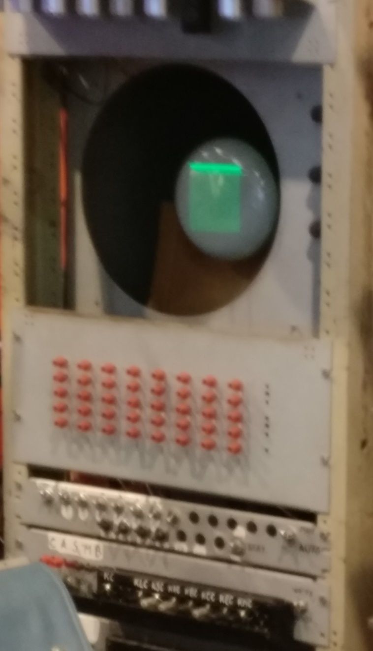
There were just 32 words of 32-but data in the first implementation of the BABy, otherwise known as the Small Scale Experimental Machine.
Here is a BlackIce implementation of the Baby:
module baby(
	input clk100,
	input button,
	output [3:0] led,
	output [7:0] led2
);

	reg [31:0] a, d;
	reg [4:0] ci, addr;
	reg [2:0] f;
	reg [2:0] state = WAITING;
	wire we, re;

	reg [1:0] counter;
	always @(posedge clk100) counter <= counter + 1;

	wire clk =  clk100; // Timing just OK for 100Mhz

	localparam WAITING = 0, SCAN1 = 1, ACTION1 = 2,
		SCAN2 = 3, SCAN3 = 4,  ACTION2 = 5,
		ACTION3 = 6, STOPPED = 7;

	line_ram ram (.clk(clk), .addr(addr), .din(a),
		.we(we), .re(re), .dout(d));

	always @(posedge clk)
	  begin
		case (state)
			WAITING: if (~button) state = SCAN1; // Doesn't work after pressing reset
			SCAN1: begin re <= 1; ci <= ci + 1; addr <= ci + 1; state <= ACTION1; end
			ACTION1: begin; re <= 0; state <= SCAN2; end // delay for BRAM
			SCAN2:
			  begin
				addr <= d[31:27];
				f <= d[18:16];
				state <= ACTION2;
				if (d[18:16]  == 3) we <= 1;
				else if (d[18:16] < 6) re <= 1;
			  end
			ACTION2: begin re <= 0; we <= 0; state <= ACTION3; end
			ACTION3:
			  begin
				state <= SCAN1;
				case (f)
					0: ci <= d;								// JMP
					1: ci <= ci + d;						// JRP
					2: a <= -d;								// LDN
					4, 5: a <= a - d;						// SUB
					6: if ($signed(a) < 0) ci <= ci + 1;	// CMP
					7: state <= STOPPED;					// STOP
				endcase
			  end
	   endcase
	  end

	assign led = {3'b000, state == STOPPED};
	assign led2 = a; // Show accumular at end of program
endmodule

module line_ram(
	input clk,
	input [4:0] addr,
	output reg [31:0] dout,
	input [31:0] din,
	input we,
	input re
);

	reg [31:0] ram [0:31];

	initial $readmemh("lines.hex", ram);

	always @(posedge clk)
	  begin
		if (we) ram[addr] <= din;
		else if (re) dout <= ram[addr];
	  end

endmodule
The 32x32bit RAM is implemented using a BRAM memory module. More information on this is in the Memory chapter.
The Baby ordered bits from least significant first. This implementation does not stick to that convention, but is otherwise a fairly accurate emulation of the Baby.
This is a disassembly of an example program. The program is loaded from the hex file lines.hex.
 0   JMP   0
 1   LDN   29
 2   STO   25
 3   LDN   25
 4   STO   26
 5   LDN   26
 6   CMP   0
 7   JMP   27
 8   LDN   31
 9   SUB   30
10   STO   25
11   LDN   25
12   STO   31
13   LDN   26
14   SUB   28
15   STO   25
16   LDN   25
17   STO   26
18   JMP   24
19   LDN   31
20   STO   25
21   LDN   25
22   STP   0
23   00000000
24   00000004
25   00000000
26   00000000
27   00000012
28   ffffffff
29   00000005
30   00000032
31   00000000
This program multiplies the numbers in lines 29 and 30 leaving the result in line 31 and the accumulator.
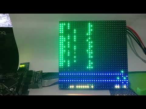
Here is a video of the led panel version of this program:

System on a chip (SoC)
A SoC is a soft processor, plus implementation of associated hardware, to produce a complete system on a chip or in our case on an FPGA chip. The hardware that is implemented as part of a SoC typically includes SPI and I2C implementations, GPIO access including LEDs, buttons, switches etc., a UART, PWM or I2S for audio output, and typically other input and output devices such as VGA monitors, LED panels, 7-segment displays, and PS/2 keyboards or mice. Access to such hardware modules is usually via a memory-mapped API.
A GNU (or other) toolchain is used to build an image file for the CPU to execute, and there needs to be some way that this can be loaded. It may be by UART, by reading from the SD card, via SPI from the STM32, or over the RPi header.
Typically, some form of configuration is required to say which hardware modules a particular instance of the SoC requires and which pins they are connected to.
Clifford Wolf produced a SoC, or more accurately, a SoC genedrator, for the icoBoard, called icoSoC. This has been modified and renamed BlackSoC to run on the BlackIce II. The next chapter describes BlackSoC.