opensourcefpgas
Open Source FPGAs using the MyStorm BlackIce II
This project is maintained by piersh
Programming the Built-in Hardware
This chapter describes how to use Verilog to access the built-in hardware on the BlackIce II board.
This built-in hardware covered consists of:
- The 4 user LEDS
- The two user buttons
- The 4 DIP switches
- The UART
Memory access including accessing the SRAM, and access to the SD card reader is covered in later chapters.
Development environment
All the projects are built using the open source icestorm tools: yosys, arachne-pnr, and icepack, and Makefiles are used to build the bit streams to configure the Ice40 FPGA.
Instructions for setting the tools up for BlackIce II are here.
Each project has its own directory contains the Verilog (.v) files, a .pcf file that maps pin names onto physical pin numbers, and a Makefile of the form:
VERILOG_FILES = <list of Verilog files>
PCF_FILE = <pcf file>

include blackice.mk
Where blackice.mk is:
chip.bin: $(VERILOG_FILES) ${PCF_FILE}
	yosys -q -p "synth_ice40 -blif chip.blif" $(VERILOG_FILES)
	arachne-pnr -d 8k -P tq144:4k -p ${PCF_FILE} chip.blif -o chip.txt
	icepack chip.txt chip.bin

.PHONY: upload
upload: chip.bin
			stty -F /dev/ttyACM0 raw
	cat chip.bin >/dev/ttyACM0

.PHONY: clean
clean:
	$(RM) -f chip.blif chip.txt chip.bin
LEDs
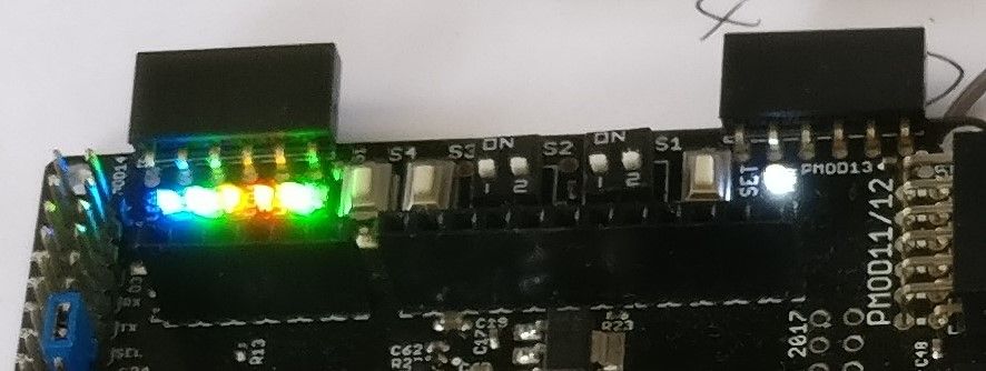
The BlackIce II board has 4 built in LEDs that are available to the FPGA:
- A blue LED, labelled LED1, with pin number 71;
- A green LED, labelled LED2, with pin number 67;
- An orange LED, labelled LED3, with pin number 68;
- A red LED, labelled LED4, with pin number 70.
Turn on an LED
You should create a development directory for running the examples in this book. Put the blackice.mk file given above in that directory.
Inside that development directory, make a directory called led, and in it add the following files.
You need a pcf file, led.pcf, to give the pin a name:
set_io blue_led 71
And a Verilog file, led.v:
module led(
	output blue_led
);

	assign blue_led = 1;

endmodule
And a Makefile:
VERILOG_FILES = led.v
PCF_FILE = led.pcf

include ../blackice.mk
Before building this example, you should do:
stty -F /dev/ttyACM0 raw
cat /dev/ttyACM0
This lets you see messages from the iceboot software when you upload bitstreams.
To run this example, type:
make upload
You should see messages on the iceboot console including the version number of iceboot and “Config done”. You may also see “Setup done” and “Waiting for serial”.
When configuration is successful the green (DONE) LED will be on and the red (DBG1) LED will be off.
Your design should then run, and the blue LED should turn on. The other LEDs may be either on or off or floating depending on their previous state. It is therefore more sensible to program all 4 LEDs as an array – see the next section.
before you run “make upload”.
If the config fails for any reason, the green (DONE) LED will be off and red (DBG1) LED will be on. DBG1 comes on while the config is in progess.
Config will fail if /dev/tyyACM0 has not been set to raw, or if the bitstream (chip.bin) is invalid in some way. After a config failure, you will need to press the reset button before you try again. Config can also fail if you have removed the jumper from the RPi header so you are in DFU and not normal mode. If can fail if the internal mux on the board is enabled and switched to the RPi header, but that only happens if you are using non-standard firmware.
Another problem that can occur on Linux machine is that a program called modemmanager is running and accessing /dev/ttyACM0. If modemmanager is installed on your Linux machine, you should uninstall it, disble it ot stop it while you are doing BlackIce development.
An array of LEDs
You can address all 4 LEDs at once. Make a directory called led and in it add:
leds.pcf:
set_io leds[0] 71
set_io leds[1] 67
set_io leds[2] 68
set_io leds[3] 70
leds.v:
module leds(
	output [3:0] leds
);

	assign leds = 4’b1111;

endmodule
Makefile:
VERILOG_FILES = leds.v
PCF_FILE = leds.pcf

include ../blackice.mk
Buttons
The BlackIce II board has two built-in buttons available to the FPGA.
- Button 1, pin 63
- Button 2, pin 64
Light an LED when button pressed
Make a directory called button and in it add: button_test.pcf:
set_io blue_led 71

set_io button1 63
button_test.v:
module button_test(
	output blue_led,
	input button1
);

	assign blue_led = ~button1;

endmodule
Makefile:
VERILOG_FILES = button_test.v
PCF_FILE = button_test.pcf

include ../blackice.mk
If you need more buttons for your project, you can buy the Digilent Pmod BTN, which has 4 buttons.
Debouncing
Accessing buttons as in the way given by the previous example is not recommended as a button takes a while to stabilise when it is pressed and if this is not programmed for, a single button press can appear as multiple presses.
Coping with this behaviour is known as debouncing the button.
There is an article on this at fpgafun.com.
To see the problem, lets implement a simple button press module and use the 4 leds as a counter:
Make a directory called bounce and add:
bounce.pcf
set_io leds[0] 71
set_io leds[1] 67
set_io leds[2] 68
set_io leds[3] 70

set_io button 63
bounce.v
module bounce(
	input button,
	output [3:0] leds
);

	always @(negedge button) leds <= leds + 1;

endmodule
We use negedge as the button is pulled low when pressed.
Build and upload in the normal way and you should see the led counter increasing by more than one per press.
To fix this, we will use the debouncer from fpgafun.com.
So, create a directory called debounce and add:
debounce.pcf:
set_io clk 129

set_io leds[0] 71
set_io leds[1] 67
set_io leds[2] 68
set_io leds[3] 70

set_io button 63
Then add the debouncer from fpgafun.com:
PushButton_Debouncer.v:
module PushButton_Debouncer(
	input clk,
	input PB,  // "PB" is the glitchy, asynchronous to clk, active low push-button signal

	// from which we make three outputs, all synchronous to the clock
	output reg PB_state,  // 1 as long as the push-button is active (down)
	output PB_down,  // 1 for one clock cycle when the push-button goes down (i.e. just pushed)
	output PB_up   // 1 for one clock cycle when the push-button goes up (i.e. just released)
);

	// First use two flip-flops to synchronize the PB signal the "clk" clock domain
	reg PB_sync_0;  always @(posedge clk) PB_sync_0 <= ~PB;  // invert PB to make PB_sync_0 active high
	reg PB_sync_1;  always @(posedge clk) PB_sync_1 <= PB_sync_0;

	// Next declare a 16-bits counter
	reg [15:0] PB_cnt;

	// When the push-button is pushed or released, we increment the counter
	// The counter has to be maxed out before we decide that the push-button state has changed

	wire PB_idle = (PB_state==PB_sync_1);
	wire PB_cnt_max = &PB_cnt;	// true when all bits of PB_cnt are 1's

	always @(posedge clk)
	if(PB_idle)
		PB_cnt <= 0;  // nothing's going on
	else
	begin
		PB_cnt <= PB_cnt + 16'd1;  // something's going on, increment the counter
		if(PB_cnt_max) PB_state <= ~PB_state;  // if the counter is maxed out, PB changed!
	end

	assign PB_down = ~PB_idle & PB_cnt_max & ~PB_state;
	assign PB_up   = ~PB_idle & PB_cnt_max &  PB_state;
endmodule
Then, to test it add debounce.v:
module debounce(
	input clk,
	input button,
	output [3:0] leds
);

	reg PB_state, PB_down, PB_up;

	PushButton_Debouncer pdb (
		.clk(clk),.PB(button), .PB_state(PB_state),
		.PB_down(PB_down), .PB_up(PB_up)
	);

	always @(posedge clk) if (PB_down) leds <= leds + 1;

endmodule
and a Makefile:
VERILOG_FILES = debounce.v PushButton_Debouncer.v
PCF_FILE = debounce.pcf

include ../blackice.mk
When you make and run this you should see the led counter increase by 1 for each button press.
Using the DIP switches
The BlackIce II board has 4 built in tiny slider switches on pins 37, 38, 39 and 41.
They can be used for configuration settings, but the pins are also used for some other purposes such as SD card access, so care must be taken using them.
If you need more switches, you can buy the Digilent PmodSwt 4 slider switch Pmod.
The following example sets the LEDs according to the switch setting.
Make a directory called switches and in it add:
switch_test.pcf:
set_io led[0] 71
set_io led[1] 67
set_io led[2] 68
set_io led[3] 70

set_io switch[0] 41
set_io switch[1] 39
set_io switch[2] 38
set_io switch[3] 37

switch_test.v
module switch_test(
	output [3:0] led,
	input [3:0] switch
);

	assign led = switch;

endmodule
And then add a Makefile and run it in the normal way.
PWM
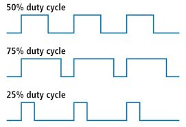
Pulse width modulation (PWM) is a technique to vary the power output on a digital pin by turning it on and off in pulses. A square wave of a specific frequency is sent to the pin and the length of time it is set high for each period is called the duty cycle.
This technique can be used to specify the position of servo motors, the speed of gear motors, or the volume of audio (see 1-bit DAC below). It is a sort of digital equivalent of specifying the voltage level for an analog output, and can sometimes be used for the same purpose, avoiding the need for digital to analog converters.
Here we will use it to set the brightness of a built-in LED.
Make a directory called LEDglow and in it add:
LEDglow.pcf
set_io LED 71
set_io clk 129
LEDglow.v
module LEDglow(clk, LED);
	input clk;
	output LED;

	reg [27:0] cnt;
	always @(posedge clk) cnt<=cnt+1;

	wire [3:0] PWM_input = cnt[27] ? cnt[26:23] : ~cnt[26:23];
	reg [4:0] PWM;
	always @(posedge clk) PWM <= PWM[3:0]+PWM_input;

	assign LED = PWM[4];
endmodule
Makefile:
VERILOG_FILES = LEDglow.v
PCF_FILE = LEDglow.pcf

include ../blackice.mk
Then run the Makefile in the normal way. You will see the blue LED glowing.
UART
The BlackIce github sites has a set of example programs including comprehensive example of use of the uart.
The uart is connected to pins 85 and 88 of the Ice40 and the RTS pin can be used as a reset and is connected to pin 128 (gReset).
The HelloWorld example using just the TX pin and gReset. It writes “Hello World!\n” to the uart at 115200 baud every one and a half seconds.
The uart_loopback example does both reading and writing. It reads from the uart and echoes back what it reads at 115200 baud.
The uart is useful for debugging Verilog program. Here is an example of using a debug module.